使用LINK180模拟索单元
Single cable simulation using LINK180 element type
I tried modelling the cale strcture with Link180 elements. The cable is divided into 20 elements. I do the following steps to analyze the strcture
1. From other resources, find the shape of the cable. Extract the coordinate of the cable and put it in the txt file. Format the txt file so that it follows the format of the ANSYS DM.
2. In ANSYS DM, read the txt file and connect the line using the points. Assemble them as part.
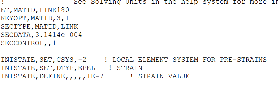
3. In the model --> geometry, add APDL commands as in the figure
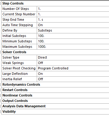
4. The analysis setting is in the figure
5. Add the gravity load
6. Insert probes in the middle of the cable
After those steps, displacement of the middle cable node in Z direction is positive.
This positive displacement doesn't make sense for me.
Then I have tried other three cases:
1. add gravity load, applied -1 N in the z direction, the model runs. But I can't trust the resutls because under gravity load, the displacement at Z direction is positive
2. add gravity load, applied -10 N in the z direction, the model doesn't run.
3. supress the gravity load, applied -1 N in the z direction, the model doesn't run.
From the above, I have several questions:
Q1: Since I have found the shape of the cable under gravity load, do ANSYS need to find the catenary shape of the cable? If do, how ANSYS find the shape. Can I extract the coordinate of the cable from ANSYS?
Q2: If I don't add the gravity load on the structure, do ANSYS consider the self-weight
Q3: Applying a concentrated load at the internal node, the model can't run? Is this is the problem of Link180 elements? How can I sovle that problem?
I have attached the single cable model below. If someone can help me answer those questions, I really appreciated!
https://www.dropbox.com/s/9obag71222axvib/single%20cable.wbpz?dl=0
Xiao
- peteroznewman edited September 2020
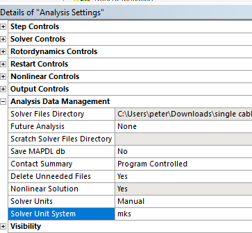
Whenever you put numbers in a Command object that require the units to be set a certain way, it is best to go to Analysis Settings and set the Solver Units to Manual and set the system correctly as I have done below. By default, the solver will use whatever the units system you left Mechanical set to. In my case, I opened your file and it was set to mm. Is the cross-sectional area property in your Command in square meters or square mm? Without making the setting I show below, you will get a different solution depending on the current units setting.
I see you are using ANSYS 19.2 and that is important to say in case someone spends time fixing your model in a later version and you won't be able to open that file.
Since this is basically a 2D problem in the XZ plane, you can help the solver out by setting all the bodies to have a Y=0 displacement boundary condition.
When I run the model, there is this warning.
*** WARNING *** CP = 0.531 TIME= 04:14:00
For element type = 1 (LINK180), KEYOPT(3) = 1 is an undocumented option.
Why are you using this?
- When ANSYS solves the Statics problem, it is searching for equilibrium of all the forces. If you have drawn a perfect catenary shape and used the correct initial strain, then the solution would make no deformation.
- ANSYS will not consider self-weight if you don't turn on the Gravity load.
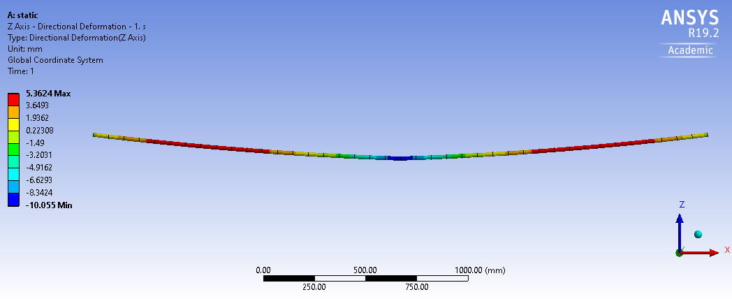
- I can get a solution with the Force in the center.
You have one line body that you meshed with 43 beam elements, then converted those to link180 elements.
I don't know if the Command that converts Beam elements to Link elements has the same effect as setting the Model Type to Link in the Details.
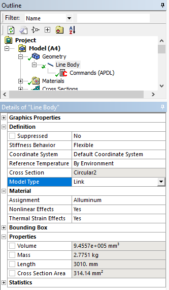
The problem is if you do that, you need 43 line bodies to be drawn in DesignModeler because you can only mesh one link element per line body.
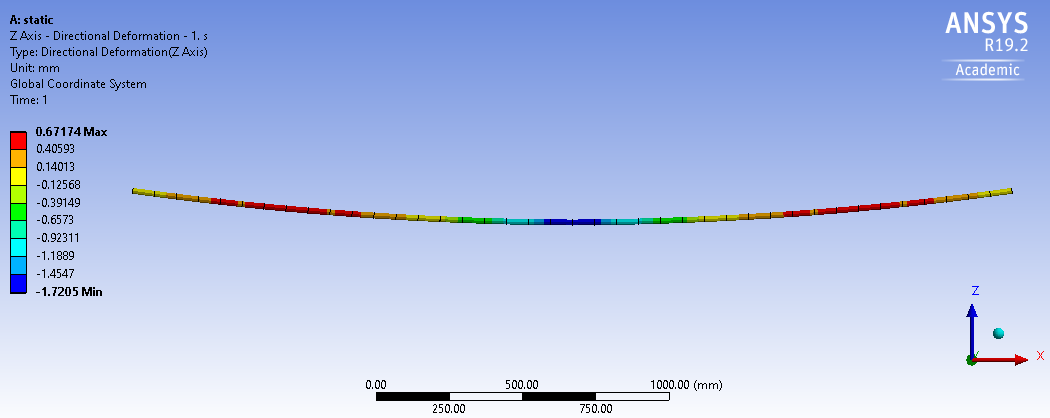
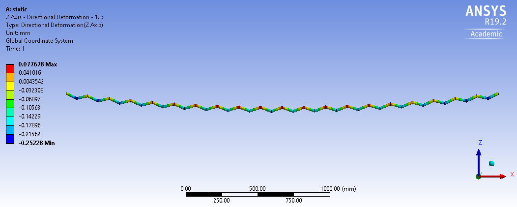
Below is the deformation with Gravity only, magnified 100 times. Maybe your initial catenary share has these errors in it, and ANSYS is providing the correct deformations. You could try drawing a straight line and then let ANSYS deflect it into a catenary shape and see what that looks like.
 This is an embed external element. It can be deleted using the delete key or the backspace key. To view the full element, press the preview button below.single cable solved.zip886.04 KB
ANSYS 19.2 archive attached.
xiao - September 2020
Hello Peter,
Thanks so much for your reply. But I still have some questions.
The unit system I use in MD and Model is mks. The cross-section of the cable is the circle2 is 3.1415e-04 m^2. I don't know why when you open my file, the unit system becomes mm. Maybe this is because when I check the results, I changed the unit into mm.
The command line 'keyopt(3)=1' is of nonsense. But this command doesn't make any change to the solutions. I added it in to my APDL command is because I paste and copy this command from previous one and forget it delete it.
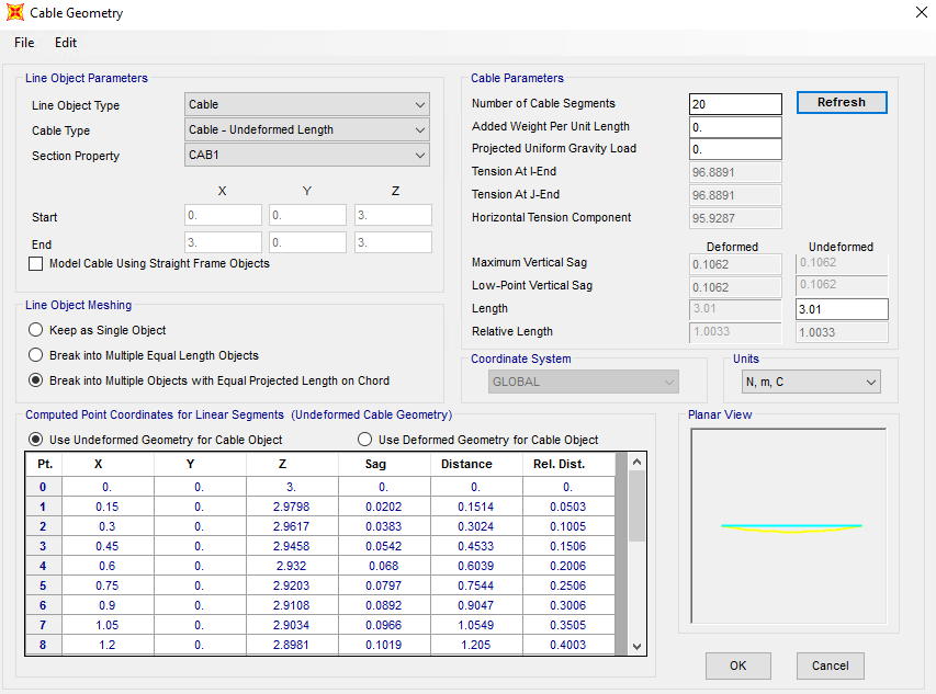
The geometry of the catenary shape of the cable I got is from SAP2000 built-in catenary element. The coordinate of the nodes and the end force is shown in the figure below.
If I understand your suggestion correctly, you suggested to change the initial strain to be the actual strain which can be calculated as F/E/A = 1.4686e-06. After I changed the strain to be that value, the displacement of the cable under gravity is still a positive value. But as you suggested, if the initial strain value is correct, the displacement of the cable under graivity should be zeros.
I ran the model in the attached file. The purpose is that I would like to see what is the displacement of the cable under -10 N or even higher vertical load. But when I increased the vertical value to -10N, the solution diverge.
Do you have more suggestions?
Sincerely,
Xiao
- peteroznewmanSeptember 2020
The model I uploaded above will solve with a -10 N Load.
- xiaoSeptember 2020
Hello Peter,
Thanks for your quick reply.
Yes, this model can run under -10N in the Z directin.From SAP2000, I calculated the catenary shape and I extracted the end force from the cable under gravity. Then I applied the initial strain under that end force (tension under self-weight). But, still, the displacement under gravity is still positive. I really confused about this point.
The APDL command i appled is based from this post https://forum.ansys.com/discussion/5740/transmission-line-simulation. From this post, the APDL commands are used just to initiate the nonlinear lateral stiffness.
Xiao
- peteroznewmanSeptember 2020
Under 10 N and gravity, the downward deformation was 10 mm, while under gravity only, the deformation upward was only 0.077 mm or 0.77% of the -10 N deformation. That is a small number. FEA solutions with less than 1% error are useful models.
- ekostson September 2020
Peter is absolutely right here. We could not expect the deformation to be exactly zero under gravity, but as pointed out something quite small, and smaller than the deflections under applied forces.
Thank you
Erik
[ANSYS] ANSYS中upcoord与upgeom的用法
[ANSYS] ANSYS中考虑初始应力的方法
[ANSYS] ANSYS错误集锦
[ANSYS] ANSYS之LINK180施加预应力及生死单元应用